


JZX90 / JZX100 Auto to Manual Geabox Connector Pinouts
If you are making your own sub-harness or re-wiring the body loom it may be useful to refer to the pinouts below as there are four combinations of wiring schemes and housings used on the A34X gearbox used in the JZX90 and JZX100 Tourer V models. The changeover point between the two types is the JZX100 Series 2 (08.1998 - 06.2001). Both connectors are 9 position however the housings are different configurations.
Regardless of year or variant, the same basic elements are required:
- Start A and Start B positions are connected to satisfy the auto ECU gearbox position start requirements
- Switched 12V Power is connected to Second gear as mapping appears to be gear dependent
- Switched 12V Power and Reverse are connected to the R154 reverse switch (not polarity sensitive)

Type 1
|
Position |
Function |
JZX90 |
JZX90 |
JZX100 |
|
X |
Blank |
|
|
|
|
2 |
Second |
Purple |
Green |
Green |
|
3 |
Low |
Green-Black |
Yellow-Green |
Yellow-Green |
|
4 |
Ignition Power |
Red-Black |
Red-Black |
Red-Blue |
|
5 |
Start A |
Black-White |
Black |
Red-White |
|
6 |
Start B |
Black-White |
Black-White |
Black-White |
|
7 |
Park |
Green-White |
Green-White |
Green-White |
|
8 |
Reverse |
Red-Blue |
Red-Blue |
Red-Black |
|
9 |
Drive |
Green-Yellow |
Green-Yellow |
Light Green |
|
10 |
Neutral |
Green-Red |
Green-Red |
White-Red |

|
Position |
Function |
JZX100 |
|
1 |
Park |
Green-White |
|
2 |
Reverse |
Red-Black |
|
3 |
Ignition |
Red-Blue |
|
4 |
Second |
Green |
|
5 |
Neutral |
White-Red |
|
6 |
Start A |
Red-White |
|
7 |
Drive |
Light Green |
|
8 |
Low |
Yellow-Green |
|
9 |
Start B |
Black-White |
Updates:
JZX90 and JZX100 Gearbox Connector Pinouts
JZX90/JZX100 Auto to Manual Swap
As the prices of all JZX Chaser, Cresta and Mark II Toyotas continue to rise, many Australians are turning to factory auto vehicles as a more affordable point of entry and then converting them to a manual gearbox. The most common manual gearboxes to use in conversions for these vehicles are the Toyota factory manual R154 and the Tremec TR56/TR6060 found in Holden/HSV models. In the USA and Canada the Nissan CD009 is a popular option, however, the comparitively high price of this gearbox in the Australian makes it a less common route. The Toyota Supra JZX80 V160 gearbox has also become too expensive for most.
This guide will use common Deutsch connectors and barrel splices to allow the use of a JZX100 R154 manual gearbox in an automatic 1995 JZX90 Chaser Tourer V base car fitted with an A340 transmission originally.
Required Signals
There are four elements of the vehicle function that need to be maintained once the gearbox has been converted:
- Start Signal
- Reverse Signal
- Driven Gear Signal
- Speed Signal
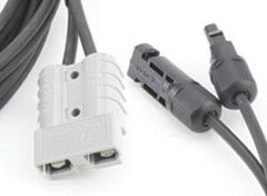
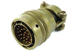
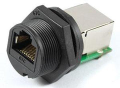
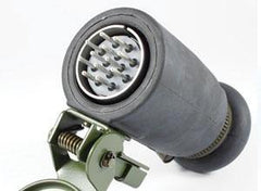
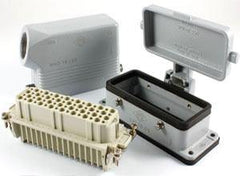
These conditions can be satisfied via re-wiring of the main 10-way gearbox plug (below, left) while the speed signal is handled separately (below, right).

To simplify the wiring setup, and DTM12 connector kit will be used to unify the gearbox and speed sensor connectors into a single point which can be assembled away from the vehicle on the gearbox and connected when the transmission is installed.
1. Start Signal
In order for the vehicle to allow start, the start circuit needs to be completed. This is done by connecting the wires on Position 5 and 6 of the large gearbox connector. On the JZX90 loom here, these are the black and black/white wires.
2. Reverse Signal
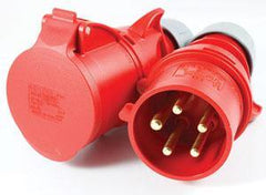
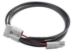
The reverse switch is located around halfway down the driver's side of the R154 and has a short pigtail terminated with bullet connectors. This needs to be connected to Ignition (Position 4) and Reverse (Position 8) on the gearbox connector which we will pass through our main DTM12. We are going to replace the bullet terminals with a more reliable and better-sealed DTM2 connector kit.
3. Driven Gear Signal
In order to have the Auto ECU operate engine control functions as if the vehicle was in a higher gear we are also going to simulate a second gear signal. This is done by joining Second (Position 2) and Ignition (Position 4).
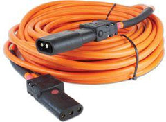
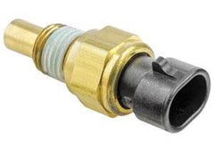
4. Speed Sensor
The instrument cluster requires a digital speed input which is provided by the speed sensor located at the rear of the R154 on the driver's side. For this sensor we will simply extend the existing wires - after passing them through the DTM12 connector - and terminate them with a new replacement OEM speed sensor connector. As the R154 being used here already had a digital speed sensor installed a new plug is the only thing required. On R154 gearboxes with a mechanical drive speedometer take-off, a conversion kit from Marlin Crawler can be used to adapt to a digital signal or a complete electronic speed sensor can be swapped in.
Factory Connector Pinout
For this install on a 1995 JZX90 Chaser Tourer V, the wiring pinout for the factory connectors can be seen below. Wiring colours may vary according to the series of JZX, however, the reverse, ignition power and start positions appear to be consistent. Please consult a service manual for your vehicle or use a multimeter and cycle the auto shifter to confirm pin positions if you are unsure.

Harness Design
From this information we can design a simply harness to combine all wires into a single junction which will make for a more serviceable solution while also upgrading the brittle factory connectors to something more rugged.
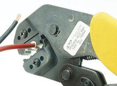
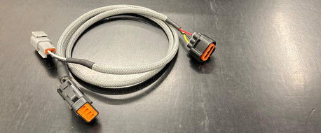
In the design below, the Start Switch wires are joined with a barrel splice to permanently complete this circuit. The Second Gear wire is spliced into the Ignition Power circuit so the ECU considers the vehicle to be in a gear which allows full range of the ignition and fuel wrap. The Ignition Power and Reverse positions are extended out to a length of 500mm and terminated with a DTM2 connector to replace the cheap, bullet terminals that were on the sensor originally and the three Speed Sensor wires were extended out to a length of 700mm and a new factory receptacle installed to allow connection to the sensor body. Click the image below to see the harness in detail.

Harness Components

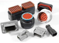
The components used to construct this harness were:
- 1 x Deutsch DTM12 Kit (DTM12)
- 1 x Deutsch DTM2 Kit (DTM2)
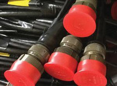
- 4 x Deutsch Sealing Plug #20 RED (0413-204-2005)
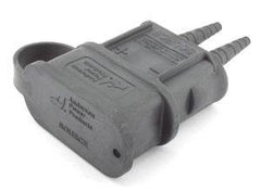
- 1 x VSS Connector Kit (TVSS3/K)
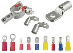
- 2 x TE Open Barrel Splice Brass 18-14AWG 0.7-2.5mm2 (63130-2)
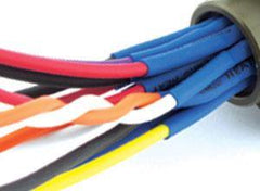
- 20AWG wire in black, green, white, red and yellow
- 1.5m PMA Braid Grey (F.66.08GR)
- 4:1 Glue-lined heatshrink (ES2000-NO.4-B7-0-STK)
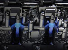
For the main junction a DTM12 way connector kit was used (in this case the black B-Key version) which combines the 9 wires of the auto gearbox connector and 3 wires of the speed circuit into one simply point of connection. For wires which do not play a role in the manual version of the loom, sealing plugs were used to ensure they are safely protected from shorting etc.
Also hidden in the 4:1 ratio heatshrink prictured below are the start circuit and second gear (green wire to black ingnition power wire) and neutral circuit barrel splices to bridge these connections.

The speed sensor wires were extended to a length of 700mm to rear from the bell housing to the rear of the R154 gearbox. The reverse sensor location is approximately 200mm further forward and it has pigtails already so only 500mm of length is required here.

To protect the cable from abrasion and heat in the transmission tunnel the fly leads where surround in PMA braid which was sealed with 3:1 glue-lined heatshrink.
