

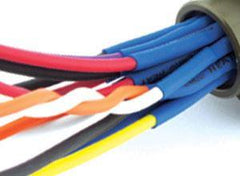
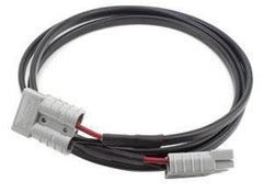


From bare cable to completed lead: crimp terminating an Anderson plug.
For all the ins-and-outs of how Anderson plugs fit together to create a reliable connection follow our Anderson Connector instructions.
HOW TO: ANDERSON CONNECTOR ASSEMBLY
We will share step by step instructions, all the way from a bare cable to crimp terminating to completing a successful Anderson plug installation. Our easy Anderson plug wiring guide will show you how to ensure you have a reliable Anderson plug connection each and every time.
In this guide we will detail the procedure to assemble a complete Anderson SB® Series connector and contacts to terminate a lead. The most common Anderson — the Multipole PowerPole assembly — is quite simple, robust and genderless, so putting them together is an easy step-by-step process.
Before we begin, let's answer the most common question we get on Anderson Plugs: which tool should I use?
Selecting the Correct Crimping Tool
Although we use the genuine Anderson 1309G4 tool in this guide and the video below, the HD16L HellermannTyton or 1309G8 Anderson crimper tool are both a popular choice for crimping Anderson Multi-Pole PowerPole connectors onto 6AWG (13.3mm2) and 8AWG (8.0mm2) wires. The following products best represent a blend of quality and affordability we have found on the market.

Whether you're using a Deutsch crimping tool or an Anderson plug crimper, all of the above hand crimp tools provide a tight, complete crimp with minimal effort. Many of these products , including the can also be used for different brands of connectors including the assembly of weather pack connectors.
To help you understand how to use the crimping tool in Anderson plug assembly, here is a short summary video of the detailed guide.
Tools Required
In addition to a pair of Anderson connectors and suitable cable, the first things you will are the correct tools.

Outer Jacket Stripper
Twin core automotive cable such as the 6mm cable we are using here has an outer jacket. The Weicon 51001007 is designed to strip flat cable (centre, top). Alternatively, you can use a box cutter (pictured) to carefully pierce the perimeter of outer jacket and remove it. We will show you how to do both.
Inner Jacket Stripper
The two inner cores have their own insulation which must also be stripped. In this example of wiring an Anderson plug we are using a Weicon 51000005 (centre, bottom).
Flat-Blade Screwdriver
A broad, flat-blade screwdriver is used to seat the Anderson contacts into the housing.
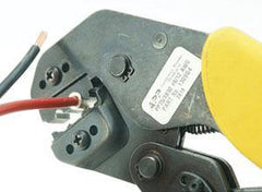
Crimp Tool
Connector-Tech ALS is a manufacturer of complete Anderson Cable Assemblies so we also recommend and sell the genuine Anderson Power Products 1309G4 Crimp Tool. This is the tool pictured in this guide.
The HellermannTyton HD16L Crimp tool is ideal for crimping Anderson plugs onto 6AWG (13.3mm2) and 8AWG (8.0mm2) wire. It represents the best blend of quality and affordability we have found on the market.
You can crimp or solder Anderson plugs, however, this is not as reliable in high-vibration environments such as a ute bed or trailer.
Step 1: Strip Outer Jacket
Strip the outer jacket from the twin core cable. We recommended removing at least 70mm of material so the inner cores can enter the housing with a straight path that doesn't introduce unnecessary strain on the cable or contacts.

If you do not have access to a flat cable stripper such as the Weicon 51001007, you can use a box cutter to make a shallow cut around the perimeter of the outer jacket and carefully pull the material off the cable. Care is needed not to go too deep as it is easy to pierce the inner cores (below, right).

Step 2: Strip Inner Cores
Use a wire stripper to strip 11mm of each of the inner cable cores. This allows the conductor to seat completely within the 50 Amp Anderson contact. Here we have used the Weicon 51000005 which can strip cable from 0.2mm to 6mm in diameter.

Step 3: Crimp Contacts
The ideal method of terminating an Anderson lead is to crimp the contact in place with the Anderson Power Products 1309G4 Crimp Tool. We use this tool on all of our cable assemblies because it creates a secure, single-indent crimp which will remain unaffected by vibration which can weaken solder joints.
The first step is to load the contact into the crimp tool. Position the contact with the blade parallel to the jaws, the contact barrel flush with the jaw surface, and the Anderson logo facing up. This will ensure the cores are not twisted when they are inserted into the housing. 'Prime' the crimp tool by squeezing it to the first detente, holding the contact in place. Insert the positive (right hand) core of the cable and crimp. Repeat the process for the second core.

There are more affordable tools available which do not meet Anderson's SB50 assembly specifications but may still provide a reliable crimp. In the absence of a crimp tool, soldering the contact in place is also an option. We recommend sizing the contact barrel as close to the conductor size as possible to minimise the amount of solder required.
Step 4: Check Polarity
Once both contacts have been crimped or soldered into place, grab your Anderson SB® Series housing and hold it with the logo facing up. Position the contacts in the housing making sure you have the polarity correct with positive side on the right.

Step 5: Insert Contacts
Place the housing on your work surface and hold the lead so that both contacts are positioned in their respective cavities. Take your flat-blade screwdriver and push firmly on the barrel of the contact so that it snaps into place. You will hear and feel when the tang is locked into place on the contact blade. Check you have seated the contacts correctly - and your crimp or solder job is satisfactory - by holding the housing in one hand and pulling firmly on the cable.

Step 6: Final Check - Mate Test
The final means of checking your contacts are completely seated is to mate your connector with another Anderson plug. If the contacts are not installed correctly the act of mating the two will eject the loose contacts from their housing. For the SB®50 Series it is only the black and grey housings which will mate together. All of the other colours are uniquely keyed.

Assembling a complete Anderson connector is a simple process if you follow the correct Anderson plug instructions and check your work at each opportunity. By terminating the cable yourself, you can customise the length of your lead to suit your exact application, whether it's fitting an Anderson plug to a car, caravan or any other application.
Useful Links
Sorry, there are no products in this collection.
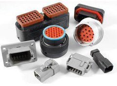
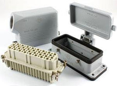
When ordering a connector it is not always as simple matter of determining between 'male' and 'female' because this can refer to both the housing gender and the contact gender. Many manufacturers offer a given housing gender with both pin and socket. A common example of such confusion occurs in the Deutsch Industrial DT range, where the plug (or male connector) actually contains socket (or female) contacts. For this reason please specify both the contact and housing gender at the time of order.
The IP Rating of a connector or accessory relates to the degree of ingress protection provided by that component. The first digit of the code relates to the degree of protection against access to hazardous parts (conductors etc) and against solid foreign objects. The second digit refers to the degree of protection against the ingress of water. For two examples of this system, consider the most commonly seen IP ratings in our products: IP44 and IP67. IP44 4: Protection from solid objects ≤1mm | 4: Protection against splashing water IP67 6: Protection from dust-sized objects | 7: Protection against immersion in water at depth of 1m for 30mins A complete guide to all IP Ratings is available here.
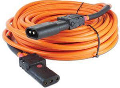
These terms are used by Phase 3 and ITT Veam on their high-current connectors.The source is considered the half of the connection from which the power is sourced; or the half supplying the electrical power. In an emergency power application, the generator is the source and would be fitted with Panel Source (panel-mount) connectors, a Panel Source Powersafe Box, or Line Source (inline) connectors on pigtails. The drain is the half of the connection which drains the power from the source. In the same emergency power application described above, the network receiving the emergency power supply is the drain and would be fitted with Line Drain connectors, Panel Drain connectors or a Panel Drain Powersafe Box.
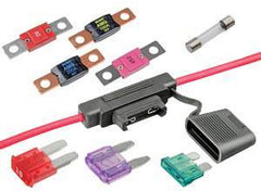
We commonly deal with both American Wire Gauge (AWG) and square millimetre (mm2) dimensions as the units used by manufacturers can vary. To convert between measurements please refer this conversion chart.
When ordering a connector it is not always as simple matter of determining between 'male' and 'female' because this can refer to both the housing gender and the contact gender. Many manufacturers offer a given housing gender with both pin and socket. A common example of such confusion occurs in the Deutsch Industrial DT range, where the plug (or male connector) actually contains socket (or female) contacts. For this reason please specify both the contact and housing gender at the time of order.
The IP Rating of a connector or accessory relates to the degree of ingress protection provided by that component. The first digit of the code relates to the degree of protection against access to hazardous parts (conductors etc) and against solid foreign objects. The second digit refers to the degree of protection against the ingress of water. For two examples of this system, consider the most commonly seen IP ratings in our products: IP44 and IP67.
- IP44 4: Protection from solid objects ≤1mm | 4: Protection against splashing water
- IP67 6: Protection from dust-sized objects | 7: Protection against immersion in water at depth of 1m for 30mins
A complete guide to all IP Ratings is available here.